
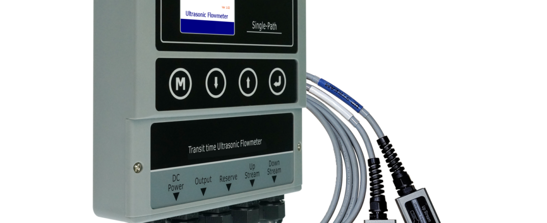
A clamp-on ultrasonic meter does its job on the pipe, but the data only becomes useful once it reaches your control or monitoring system — a PLC, a building management system (BMS/BAS), a SCADA platform, a data logger, or the cloud. Fixed clamp-on meters offer several output channels, and choosing the right one is a common source of confusion. This guide explains each output, what it is good for, and how it is wired. If you are still deciding on the instrument itself, start with our clamp-on flow meter overview and application selection guide.
The Four Main Output Types
1. 4–20 mA analogue output
The classic industrial analogue signal. The meter represents flow rate as a current loop: 4 mA = zero flow, 20 mA = the configured full-scale flow, with every value in between proportional.
- Wiring: two wires to an analogue input card on the PLC/BMS; the loop is powered from the meter or the controller depending on configuration.
- Best for: feeding instantaneous flow rate into a PLC or BMS for indication, trending and PID control loops. Universal support — every modern controller has 4–20 mA inputs.
- Limits: one variable per channel (flow rate; a second channel can carry energy or velocity), and resolution/accuracy is limited by the analogue conversion (typically ~0.1% full scale). It does not carry totalised volume.
2. Pulse / OCT (open-collector transistor) output
A solid-state switch that closes once per a set volume of flow — e.g. one pulse per litre or per 10 litres. The pulse frequency is proportional to flow rate and the pulse count equals total volume.
- Wiring: two/three wires to a high-speed counter or digital/pulse input on the PLC, a separate batch totaliser, or an energy/billing unit. OCT is an open-collector transistor (isolated), not a mechanical relay.
- Best for: totalisation and billing/allocation — counting pulses gives accumulated volume with no drift, making it ideal for water accounting, batch control and energy-meter pulse inputs.
- Tip: set the pulse volume (litres/pulse) to match the counter’s max frequency at your highest flow rate.
3. RS485 Modbus RTU
A serial data link running the Modbus RTU protocol over an RS485 two-wire (plus common) bus. Instead of one analogue value, the controller can read every parameter in the meter: flow rate, velocity, totalisers (forward/reverse/net), signal quality, temperature, energy (on YF-E6), alarms and status.
- Wiring: a shielded twisted pair (A/B + common/com) daisy-chained to a Modbus/RS485 port on the PLC, BMS gateway, data logger or a Modbus-to-ethernet/MQTT converter; each meter gets a unique slave address and baud rate.
- Best for: rich integration — pulling multiple variables and diagnostics into SCADA/BMS over a long-distance, noise-immune bus (up to ~1.2 km). This is the most information-rich hard-wired option; the meter’s Modbus register map maps each value to an address.
- Multiple meters can share one RS485 bus (different addresses), saving cabling on multi-point sites.
4. GPRS / 4G (cellular) cloud logging
Premium meters such as the YF-C8 offer an optional built-in or external GPRS/4G module that pushes flow data to a cloud platform over the cellular network — no local controller or cabling required.
- Best for: remote, unmanned or distributed sites — water network DMA metering, pump stations, district energy, pipelines — where running cable to a PLC is impractical. View flow, totals and alarms in a web dashboard, and receive threshold alarms by SMS/email/app.
- Needs: a SIM card with local cellular coverage and power at the meter; data is logged locally and uploaded on schedule.
- This is the easiest route to remote monitoring without integration work; it can coexist with wired outputs.
Comparison at a Glance
| Output | Carries | Wires to | Typical use |
|---|---|---|---|
| 4–20 mA | Instantaneous flow (1 var/channel) | Analogue input (PLC/BMS) | Indication, control loops |
| Pulse / OCT | Volume (count) / rate (freq) | Pulse/counter input | Totalisation, billing, batch |
| RS485 Modbus RTU | All variables + diagnostics | Modbus serial port / gateway | SCADA/BMS rich integration |
| GPRS / 4G | All data to cloud | Cellular (SIM), no local wiring | Remote/unmanned monitoring |
Which Should You Use?
- Simple flow-rate display/control on a PLC or BMS → 4–20 mA. Fastest to commission, universally supported.
- Need total volume for billing, allocation or batch totals → pulse/OCT into a counter (often used alongside 4–20 mA).
- Want rate + totals + signal status + energy in SCADA/BMS over one cable → RS485 Modbus RTU (best data-to-wiring ratio; standard on YF-C6/YF-C8/YF-E6).
- Remote site with no local control system → GPRS/4G cloud (YF-C8 option).
- Energy/BTU monitoring → the YF-E6 energy meter outputs both flow and thermal energy (kWh/BTU) over the same channels — see how BTU metering works.
Integration Best Practice
- Use shielded twisted-pair cable for 4–20 mA and RS485; ground the shield at one end and route away from VFD/motor power cables to avoid noise (electrical interference is also a reading-stability cause — see troubleshooting).
- Match the meter’s full-scale and pulse-value settings to your controller’s ranges, and confirm the Modbus baud rate, parity and slave address on both ends.
- Note that portable meters (YF-P1/YF-P2) are standalone logging tools (SD/USB) rather than permanently wired instruments — use a fixed model for control-system integration (portable vs fixed).
- Correct readings start with a correct install — output wiring cannot fix an acoustic problem; accuracy setup is covered in the accuracy factors guide. Pin-outs and the Modbus register map are in the manuals on the Downloads page.
Frequently Asked Questions
What output do I need to send flow to a PLC or BMS?
For a simple instantaneous flow signal, use the 4–20mA analogue output to an analogue input — it is universally supported and quick to commission. For total volume/billing, add the pulse/OCT output to a counter input. For the richest integration (rate, totals, signal status, energy and alarms over one cable), use RS485 Modbus RTU to a Modbus port or gateway on the PLC/BMS/SCADA.
Can a clamp-on meter send data to the cloud without a PLC?
Yes. Premium models like the YF-C8 offer an optional GPRS/4G cellular module that pushes flow, totals and alarms to a web cloud platform using a SIM card — no local controller or signal cabling needed. This is ideal for remote, unmanned or distributed sites such as water network points, pump stations and district-energy lines.
What is the difference between the pulse output and Modbus?
The pulse/OCT output gives volume as pulses (one pulse per configured unit volume) — great for simple totalisation and billing into a counter, and frequency represents flow rate. Modbus RTU over RS485 is a digital data bus that lets the controller read every meter parameter (flow, velocity, forward/reverse totals, signal quality, energy, alarms) with diagnostics, and lets multiple meters share one cable. Pulse is simplest for totals; Modbus is most comprehensive.
Need the Right Outputs for Your Control System?
YS-Flux fixed clamp-on meters (YF-C6, YF-C8) and the YF-E6 energy meter support 4–20 mA, pulse/OCT, RS485 Modbus RTU and optional GPRS/4G cloud logging. Tell us your controller (PLC/BMS/SCADA), required signals and whether you need remote logging — our engineers will specify the exact output configuration and provide the Modbus register map within one business day. Request a Quote →