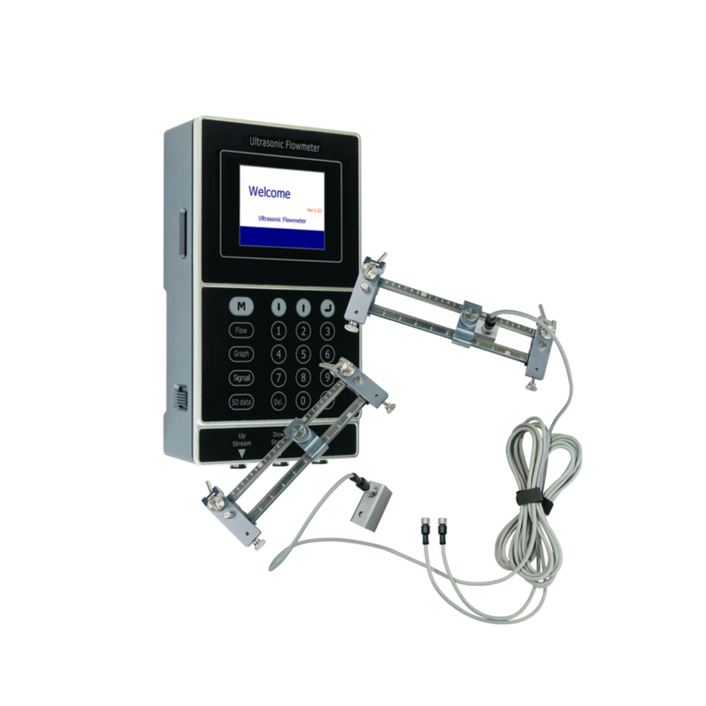
A clamp-on ultrasonic flow meter is only as good as its mounting. The electronics are forgiving; the installation is where accuracy is won or lost. This guide condenses the rules our engineers apply — they also ship with every YF-P1 and YF-P2 portable unit.
Step 1: Choose the Right Location
Ultrasonic meters need a symmetrical, undisturbed velocity profile. Keep transducers away from flow disturbances:
- ≥ 10 × pipe diameter (10D) of straight pipe upstream of the mounting point after elbows or tees;
- ≥ 5D straight downstream;
- ≥ 30D after valves and ≥ 50D after pumps — these distort the profile badly;
- Prefer a horizontal run with the transducers mounted side by side on the side of the pipe (3 and 9 o’clock), never on the very top where air bubbles collect or the very bottom where sediment sits;
- The pipe must be completely full. Avoid vertical runs with downward flow and outlets that drain partially full.
Step 2: Prepare the Pipe Surface
Sound must travel through the pipe wall cleanly:
- Remove loose paint, rust and scale where the transducers will sit; a filed smooth patch is ideal (dense intact paint ~0.5 mm can stay);
- Remove pits and dents — coupling gel fills microscopic gaps, not craters;
- Mark the exact transducer positions and keep them on the same pipe axis.
Step 3: Choose the Mounting Method
- V-method (reflect) — both transducers on the same side, signal reflecting off the far wall. Best accuracy for DN25–DN400. The default choice.
- Z-method (direct) — transducers opposite each other, signal travels straight across. Use for large pipes (DN100–DN5000) or weak signals (old, scaled or lined pipes).
- N / W-method — extended multi-reflection paths that improve sensitivity on small pipes under ~DN50.
Enter the pipe material, outer diameter and wall thickness into the meter; it computes the exact transducer spacing. Apply couplant evenly, press the transducers on, and strap or clamp them firmly — movement of even a millimetre shifts the signal.
The Mistakes That Ruin Readings
- Mounting too close to an elbow, valve or pump;
- Leaving thick, loose or air-gap paint under the transducer;
- Too little couplant, or transducers loose enough to vibrate;
- Partially filled pipe or air pockets at the top of the line;
- Ignoring the flow-direction arrow, giving negative readings that confuse logs.
Step 4: Verify Before You Trust
Check the signal strength / signal quality (SQ) value on the display — healthy installations typically show SQ ≥ 50 and stable readings. If the signal is weak: improve the surface, switch V→Z method, or try the other pipe side. Portable units make this verification quick — that is exactly why survey teams carry the YF-P1.
Full manuals and dimension drawings for all models are available on our Downloads page.
Frequently Asked Questions
Why does my clamp-on meter show unstable readings?
The usual culprits: insufficient straight run, a partially full pipe, poor surface preparation, transducers drifting on their straps, or gas bubbles in the liquid. Work through location → surface → coupling → method in that order.
Can I install the transducers on a painted pipe?
Yes, if the paint is dense and intact (~0.5 mm). Loose, thick or flaking paint must be removed down to bare metal for reliable signal transfer.
V-method or Z-method — which should I use?
Start with V-method for DN25–DN400. Switch to Z-method for large pipes or when the V-signal is weak. Small pipes below DN50 benefit from N/W methods that lengthen the acoustic path.
Related Reading
- Installing Without Shutting Down the Pipeline
- No Signal / Unstable Reading? Troubleshooting
- Factors That Affect Clamp-On Accuracy
- Which Pipe Materials Can Be Measured?
- What Pipe Size Can a Clamp-On Meter Measure?
Need Help Selecting a Flow Meter?
YS-Flux manufactures clamp-on ultrasonic flow meters for wholesale, export and OEM/private-label partners. Tell us your pipe size, liquid and application — our engineers will recommend the right model and quote within one business day. Request a Quote →
Browse our complete range on the Products page.
Questions about your application? Contact our team or request a quote — we respond within 24 hours.